![[photo]](images/cat/subs/monolith.gif)
DieselNet Technology Guide » Emission Control Catalysts
DieselNet | Copyright © ECOpoint Inc. | Revision 2022.11
This is a preview of the paper, limited to some initial content. Full access requires DieselNet subscription.
Please log in to view the complete version of this paper.
Many of the early automotive catalytic converters in the 1970s utilized pellet or bead-shape supports. A volume of spherical particles (pellets) made of gamma-alumina, 2.5 to 5 mm in diameter, was placed into a steel shell and contained between two screens to form the catalytic converter. The noble metal catalyst and stabilizers were incorporated into the pellets. That catalyst design originated from catalytic reactors used in the chemical processing industry. Pelleted catalysts had several disadvantages including high pressure drop and gradual catalyst loss due to attrition. Monolithic honeycombs, which were developed to address the shortcomings of pelleted supports, have become the standard substrate in today’s automotive, diesel, and other emission control catalyst applications.
Monolithic catalyst supports are honeycomb structures with many small, parallel channels running axially through the part. They are sometimes called “flow-through” substrates. The cross-section is typically circular or oval, but asymmetric contours are also manufactured. Exhaust gases flowing through the channels contact the catalyst which is deposited on the channel walls. Major advantages of monolithic supports include high geometric surface area (GSA) per unit volume (compactness), large open frontal area (low pressure drop), and excellent attrition resistance.
Monolithic catalyst substrates (Figure 1) are made of ceramics or metal. Ceramic substrates (honeycombs) usually have square cells, while most metallic substrates have sinusoidal channels. Other channel cross sections are possible, including triangular, hexagonal, trapezoidal and round. The number of cells can vary between 10 and over 1000 cells per square inch (cpsi). Parts that were commercially used for internal combustion engine applications in the 1990s had cell densities between 200 and 600 cpsi, with 400 cpsi being the most common cell density in gasoline car applications. Since then, increasingly higher cell densities have been introduced in gasoline cars, with parts in excess of 1000 cpsi being available in both the ceramic [320] and metallic designs [876]. Most substrates for diesel applications upstream of a particulate filter remain in the 300-400 cpsi range, while 600 cpsi and higher densities can be used for catalysts located downstream of a particulate filter.
![[photo]](images/cat/subs/monolith.gif)
Compared to materials used in catalysis, the walls of ceramic honeycombs have large pores and very low specific surface areas of about 0.3 m2/g. Foils used for metal substrates have no porosity. Since high surface area carriers are required for catalysts, it is necessary to deposit a high surface area coating onto the channel walls. That coating, called the washcoat, is composed of porous, high surface area inorganic oxides such as gamma-Al2O3. The specific surface area of the catalyst washcoat materials is typically above 100 m2/g. Noble metal catalysts, such as platinum, are deposited on the surface and within the pores of the washcoat. Exhaust gases in a catalytic converter diffuse through the washcoat pore structure to the catalytic sites where catalytic reactions occur.
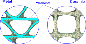
The washcoat layer on a metallic foil and on a ceramic substrate is illustrated in Figure 2. The thickness of the washcoat layer is on the order of 20-40 µm. Much thicker washcoat deposits (“fillets”) are formed in the cell corners, especially in the sinusoidal channels of metallic substrates. These fillets may lead to a less productive use of precious metals. To minimize this effect, an optional corner-fill layer can be applied directly on top of the substrate, underneath the proper washcoat [5660]. In some metal substrate technologies, the metal foil is washcoated prior to forming the honeycomb. These technologies produce clean channels with no fillets in the corners but tend to compromise the mechanical strength and durability of the substrate.

Other, non-cellular monolithic substrates have also been researched for catalyst applications. Popular designs included various rigid foams made of cordierite, silicon carbide [875], or metal [170]. Compared to the honeycomb monoliths, these products have low geometric surface areas and/or high pressure drop. They found very limited commercial use as catalyst substrates.
###