Conference report: CIMAC Congress 2023
30 June 2023
The 30th CIMAC World Congress was held in Busan, Korea on June 12-16, 2023. The event, originally planned for 2022, was delayed due to the Covid-19 travel restrictions. The CIMAC Congress, organized once every three years, is a major technical meeting that covers internal combustion engine technology for ship propulsion, power generation, and rail traction. This year, the program included over 200 technical papers presented in four parallel sessions, as well as several discussion panels, poster sessions, social events, and technical tours—including a tour of the Hyundai Heavy Industries (HHI) marine engine assembly plant at the company’s Ulsan shipyard. The Congress also included an exhibition showcasing engine components and related products. The meeting was attended by more than 700 participants from 28 countries.
Please log in to view the full version of this article (subscription required).
The main theme during this years’ Congress was decarbonization of large internal combustion engines (ICE) such as those used in marine and power generation applications. A large number of papers were devoted to such prospective alternative fuels as hydrogen, ammonia, and methanol. Other topics, traditionally covered by CIMAC, included diesel and natural gas engines, engine components and subsystems, combustion, fuels, emissions and emission control, as well as digitalization of shipping.
Decarbonization
As there are no viable powertrain alternatives for high-power ICEs, it is envisioned that the reduction of GHG emissions from marine and other large engines can be achieved by ‘defossilizing’ the fuel. E-fuels, produced with renewable energy by Power-to-X (PtX) synthesis, are considered the key fuel decarbonization technology. E-fuels are currently not commercially available at scale and not economically viable—according to various estimates, e-fuels would cost three to five times more than fossil fuels. A fuel price model by Rolls-Royce predicts that the prices of e-fuels would decline rapidly in the future, following a massive scale-up of production [5821]. According to the Rolls-Royce model, e-fuel prices would match those of biofuels by 2030, and those of fossil fuels by around 2040.
The sole voice of caution about the anticipated switch to much more costly synthetic fuels came from the shipping industry. CMA Ships highlighted the technical and regulatory uncertainties on the path to decarbonization [5897]. Since the future low-carbon fuels that are being considered are not an energy source but merely energy carriers, the transition to low-carbon shipping will likely face energy supply limits. CMA Ships is currently testing carbon capture, utilization, and storage (CCUS) technology onboard ships—an alternative approach to carbon emission reduction. However, preliminary results indicate that CCUS also involves a significant energy cost and a fuel economy penalty.
Most engine manufacturers have initiated alternative fueled engine development, to be able to supply customers who wish to pursue decarbonization goals. The main prospective future fuels for marine engines include ammonia and methanol. While hydrogen is generally not considered a suitable marine engine fuel, a number of papers have also been presented on hydrogen engine development.
Ammonia and Hydrogen as Fuels. Ammonia and hydrogen are outliers in ignition and combustion characteristics and show several ‘anomalies’ compared to liquid and gaseous hydrocarbon fuels. Compared to each other, H2 and NH3 are the opposites: while hydrogen exhibits a very wide flammability range and high flame speeds, ammonia suffers from a narrow flammability range and low flame speed. Ammonia properties that affect diesel cycle combustion include a high auto-ignition temperature and high heat of vaporization. Ammonia is also highly toxic, which presents a problem in laboratory experiments as well as in potential future applications. At this time, there are no commercial engines that can run on neat hydrogen or ammonia—commercial implementations are limited to natural gas engines that can accept a certain level of H2 substitution.
Papers on NH3 and H2 combustion were presented by AVL [5891], MAN Energy Solutions (MAN ES) [5892][5893], Japan Engine Corporation [5894], Wärtsilä [5895], LEC [5896] and others. All of the presented data had a preliminary character. A wide range of ignition and combustion concepts have been tested. Spark-ignited, port fuel injected systems would be favorable for fast-to-market approaches (in case of NH3, about 5% of H2 ignition promoter is needed). A number of other approaches were reported, including low- (Otto) and high-pressure (Diesel) direct injection with diesel pilot ignition, pre-chamber configurations, and stratified ammonia injection.
Emissions from H2 engines include NOx, while NH3 combustion produces unburned ammonia, NOx, and N2O emissions. Depending on the stringency of applicable emission regulations, highly efficient aftertreatment systems may be required with both types of fuels.
An unorthodox hydrogen ICE concept, called the Argon Power Cycle (APC), was developed by WTZ Roßlau [5887]. The concept involves the use of argon as an inert gas circulation medium, Figure 1. Hydrogen and oxygen produced from water electrolysis are injected upstream of the combustion chamber, while the water vapor produced during combustion is removed by condensation, thus avoiding the release of any gaseous emissions. Preliminary engine tests were conducted in a modified 3-cylinder Ford EcoBoost engine.
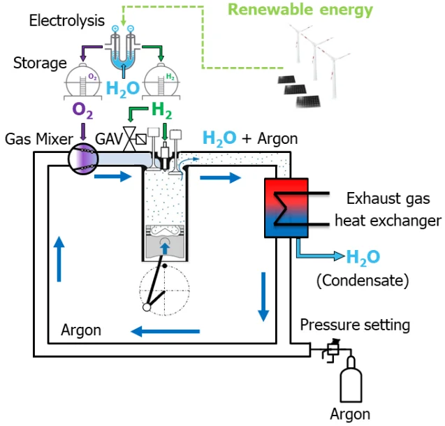
Closed circulation engine with argon as the working gas
Engines
New Gas Engines. A pre-chamber (PC), spark-ignited combustion system is common in many lean-burn natural gas engines in the medium-speed range. These PC systems can provide high thermal efficiency, however, since the mixture in the pre-chamber is nearly stoichiometric, it contributes to NOx emissions—the pre-chamber combustion can contribute as much as 75% of the total NOx emissions from lean burn gas engines. These NOx emissions can be reduced by reducing the amount of gas injected into the pre-chamber, but leaner PC mixtures increase the cylinder pressure fluctuation and narrow the stable combustion area. Studies by Daihatsu [5817], Hanshin Diesel [5818], and Kyushu University [5819] looked into ways to achieve stable combustion in engines with a lean pre-chamber. The work by Daihatsu involved the development and validation of a knock prediction model, and produced modified specifications of the pre-chamber, the main chamber, as well as intake ports and gas nozzles. In the Hanshin Diesel engine, two pre-chambers were introduced in one cylinder for redundancy.
Innio Jenbacher presented their updated Type 3 Gas Engine platform, with a newly developed software and hardware package and a 4-valve cylinder head and a spherical piston bowl. The engine efficiency was increased by an average of 0.3% points, while electrical efficiency increased by 1.5 to 2.5% points, depending on engine version. In power generation applications, the new engines feature a 43% electrical efficiency at full power output. HC emissions were reduced by 30% through crevice volume optimization (12%) and skirt guidance improvement, combustion bowl, and piston geometry changes (18%) [5820].
AVL reported on the development of a large, high speed engine platform, targeting peak firing pressures of up to 330 bar and BMEP capability up to 35 bar [5883]. The performance targets include diesel BSFC of 168 g/kWh for a 50 Hz continuous genset rating with 170 kWm/cylinder; diesel BSFC of 172 g/kWh for a standby power generation and marine rating of 270 kWm/cylinder; and gas efficiency of > 50% for an electrical power generation rating of 210 kWm/cylinder. AVL designed a new clean sheet engine power cylinder unit (bore 175 mm, stroke 215 mm) and presented preliminary test results in diesel, gas (gas-fed prechamber with spark ignition), and gas with H2 fumigation configurations.
Dual Fuel Engines. MAN ES discussed their MAN 49/60DF engine [5884]. The nominal rating is 1,300 kW/cylinder and operation is nominally at 600 rpm. The portfolio covers stationary applications with V-type engines up to 26 MW and marine applications with L- & V-type engines up to 18.2 MW. Features include two-stage turbocharging, 3-position active inlet valve phasing, Common Rail 2.2 (CR2.2), a new deep-bowl combustion chamber and closed-loop combustion control system enabling increased power and efficiency. Two sets of injectors, pilot fuel injectors for dual fuel operation and diesel injectors for diesel-mode operation, are used. Gas is introduced through port injection. Pilot injection amounts range from about 2% at 100% output to about 9% at 25% output. The three positions of the VVT in gas operation allow optimized Miller-timing at high-load, improved trade-off between HC-emissions and specific gas consumption at part-load, and a reduction in pilot fuel oil consumption. The Adaptive Combustion Control system (ACC2.0) uses in-cylinder-pressure and NOx sensor measurements to optimize cylinder balancing, heat release shaping, dynamics and knock control and can compensate for variations in main and pilot fuel quality (i.e., cetane number), ambient conditions such as humidity, and wear and aging effects.
The Yanmar 6EY26DF dual fuel engine [5885]—in addition to diesel mode and dual fuel operation—is also capable of mixed cycle operation where a relatively large amount of diesel fuel is used to ignite gas that is premixed with the intake air. One benefit of the latter mode of operation is that it can reduce the need for using a gas combustion unit when gas calorific value and pressure are unstable, such as immediately after bunkering or during maintenance of the LNG supply system.
WinGD highlighted the performance improvements from the use of low-pressure EGR system on the X-DF2.0 dual-fuel engine [5886]. For the X-DF1.0, which operates without EGR, pre-ignition via burning lube oil droplets limited engine performance. Investigations revealed that cooled EGR leads to faster quenching of burning lube oil droplets that can suppress pre-ignition. This, combined with cooled EGR’s ability to suppress knock allowed for an increase in compression ratio that resulted in a reduction in IMO weighted gas consumption of about 5.5 g/kWh and an efficiency improvement of 2% points. Additionally, recirculating up to half of the exhaust gas “recycles” the unburned hydrocarbons in the EGR mass flow to reduce methane slip as well as the well known reduction in NOx emissions due to EGR. The IMO weighted CH4 and NOx emissions are reduced by 45% and 35% respectively. The increase of the engine efficiency together with the reduction of the CH4 emissions led to a drop in GHG emissions by about 10%.
Turbocharging
MAN ES discussed the development of a new radial turbocharger generation, including two new radial turbocharger series: TCP (P for Pressure) and TCF (F for Flow) [5882]. This new radial turbocharger generation pushes the limits towards single stage pressure ratios above 6 and a best-in-class specific mass flow rate. Another objective of the development is compatibility with future synthetic fuels.
Accelleron (Turbo Systems Switzerland, formerly ABB Turbocharging) presented their new turbocharger platform, A101-R turbocharger series, intended for modern large high-speed diesel engines—such as those in highly loaded variable-speed mining machinery, marine propulsion systems, and high power density generator sets [5826]. The product concept is based on a common core unit consisting of a newly developed turbine stage with enhanced part load performance, while for the compressor side a modular design approach has been taken. For example, the compressor can be specified for high pressure single stage turbocharging systems, or alternatively for 2-stage turbocharging systems, when higher overall pressure ratio is required. The development includes two frame sizes and is in the final stages to have the commercial product release of the water-cooled units by mid-2023 and the oil-cooled versions by the end of 2023.
In another paper, Accelleron analyzed potential impacts of new and alternative fuels—such as hydrogen, ammonia, and methanol—on turbochargers [5881]. It was concluded that the fuel type has no major impact on the basic turbocharger layout. The fuel , however, has an impact on the operating conditions of the turbocharger. For instance, component matching (compressor and turbine) differs substantially between methane and ammonia. This may be a source of problems in dual fuel engines—an engine bypass may be needed in the ammonia mode. The new fuels would also have material impacts, as ammonia is corrosive to copper alloys used in turbocharger bearings, while methanol can promote corrosion by formic acid.
Fuel Injection & Combustion
Wabtec presented an update on the development of the cooled spray technology—an approach to enhance mixing upstream of the lift-off length of the spray by injecting additional air near the fuel injection nozzle outlet. The Wabtec implementation of this approach uses a monolithic insert installed in the cylinder head that mounts over the fuel injection nozzle and contains multiple fuel and air passages, Figure 2. The improved fuel-air mixing has the potential to significantly reduce soot formation in diesel engines [5822].
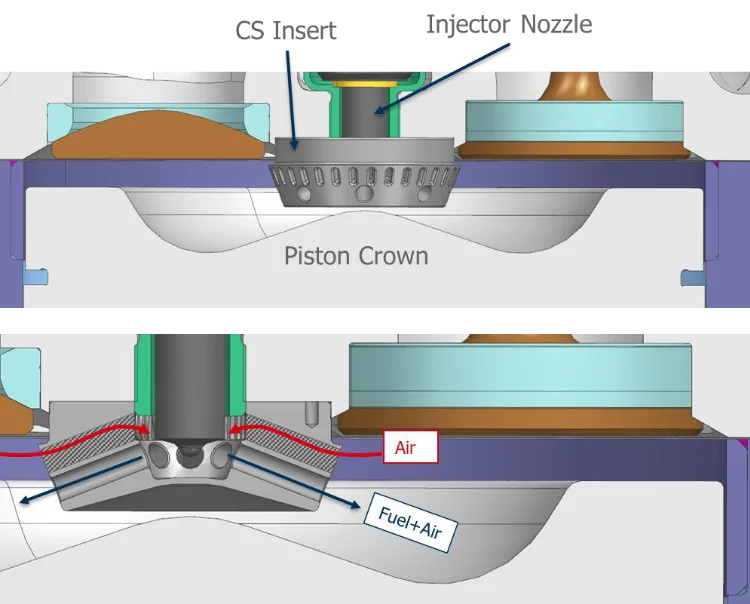
(Courtesy of Wabtec Corporation)
Several cooled spray prototype inserts were tested on a large-bore medium-speed single-cylinder engine at 13.5 bar and 25.5 bar IMEP with EGR in the range of 30-35%. One of the tested designs achieved a 30-50% PM emission reduction at medium loads, and PM reductions greater than 50% at high load. At constant US Tier 4 locomotive emission levels, cooled spray could also enable fuel savings on the order of 2%. A key challenge with the technology is to precisely align the CS insert with the fuel injector.
Bosch discussed a method using injector-internal pressure sensor to control individual cylinder injection to achieve optimal combustion and efficiency [5873]. As with other injectors for large engines, pressure in the nozzle needle control volume is monitored.
Several talks covered the development of fuel injection systems for various prospective future fuels which can be toxic, have low lubricity, high vapor pressure and a risk of cavitation, and can promote corrosion. Woodward [5874] presented the development of their SOGAV low pressure gas admission valves capable of hydrogen and gaseous ammonia. DUAP [5875] talked about the development of gas and/or hydrogen high pressure DI injectors capable of up to 500 bars. OMT [5876] and Heinzman [5877] discussed fuel injectors for handling of liquid ammonia and methanol fuels, while Wärtsilä [5878] highlighted the development of a retrofittable cryogenic fuel injection system for LNG, ammonia, and hydrogen.
GHG Emissions Control
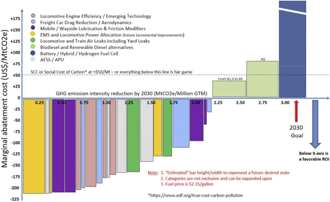
The Southwest Research Institute (SwRI) presented several papers pertaining to GHG emission reduction from railroads and locomotive engines. North American freight railroads collectively use on the order of 13.6 billion liters of diesel fuel each year [5827]. Each of these railroads have recently announced GHG emission reduction targets under SBTi (Science Based Target initiative) as a step toward low-carbon freight transportation. These railroads have made consistent and steady improvements in fuel efficiency over the last decade, on the order of 1% per year as an industry, but additional fuel efficiency gains will need to be even more aggressive to meet the SBTi goals of roughly 30% reduction of Scope 1 GHG emissions intensity by 2030. Some recent initiatives to reduce GHG emissions are Energy Management Systems (EMS) and lower Horsepower-Per-Trailing-Ton (HPTT) due to longer trains enabled by Precision Scheduled Railroading (PSR) initiatives. Auto Engine Stop Start (AESS) and the use of Distributed Power (DP) technology is also listed as being in common practice. Less common approaches are the use of biofuels (biodiesel and/or renewable diesel), use of data analytics, having a fuel dispatching desk as part of their network train dispatching process, track lubrication and motherslug units. Current pace of improvement will not be sufficient to meet 2030 goals. Figure 3 illustrates the many technical improvements that would need to be adopted to reach this goal.
In another study, the SwRI tested the effect of renewable diesel and its blends with CARB diesel, US EPA certification diesel, and biodiesel on emissions and fuel economy in a US Tier 3 GE ES44C4 locomotive [5824]. Renewable diesel was shown to reduce tailpipe emissions of NOx, PM, CO, HC, and CO2. Additionally, due to its lower carbon intensity, renewable diesel has the potential to greatly reduce overall GHG emissions from locomotives. However, due to the lower volumetric energy density of renewable diesel and biodiesel (the R100 is 4.9% lower than the EPA certification diesel and the B100 fuel is 8.6% lower), significant penalties to volumetric fuel consumption were seen—there is a financial penalty associated with running renewable diesel, even if the price per liter is equivalent. While no loss of engine power was noted on any fuel blend tested, there is a possibility of reduced power at higher throttle notches with certain engine control systems, as significantly higher volume of fuel is required using renewable and biodiesel blends.
One potential option to reduce carbon emission from diesel engines is to replace some of the diesel fuel with hydrogen fumigation. This approach was studied on a US EPA Tier 2 Cat 3512 diesel engine, with a rated power of 1 MW at 1750 rpm [5863]. The experiments showed that carbon-related emissions (CO, HC) were reduced with increasing H2 substitution, but with a diminishing benefit, as diesel combustion was deteriorating at higher hydrogen fractions. NOx emissions did not change with H2 substitution, but the NO2 fraction increased up to nearly 50% of the total NOx at 30% H2 energy. It was also shown that lifecycle GHG emissions could only be reduced using low-carbon hydrogen. Replacing diesel with high carbon intensity H2, such as typical industrial H2 made via steam methane reforming, actually increases GHG emissions.
Methane Emissions from NG Engines. Several papers were devoted to CH4 emission control from medium-speed natural gas dual-fuel engines. Finland’s VTT presented an in-depth literature review of methane slip emissions from LNG vessels [5866]. The study, conducted as part of the EU Green Ray project, found that methane slip from marine engines can range from 1.9 to 6 g/kWh CH4, with some of the lowest values emitted by a new technology Wärtsilä 31DF dual-fuel engine.
While the VTT findings have already been reported on DieselNet, a new paper by Wärtsilä shed some light on the methane reduction technology used in their new 31DF dual-fuel, lean-burn Otto engine [5867]. The main CH4 control strategy involves spatially distributed, stable ignition control referred to by Wärtsilä as controlled “knocking event” (the engine does not use EGR or aftertreatment for CH4 control). Tests on the Aurora Botnia ferry, conducted over more than 1,000 hrs of operation, showed emission reductions of 60% for CH4, 90% for NOx, and 13% for CO2.
The in-cylinder techniques to control methane emissions from dual-fuel engines applied by Hyundai Heavy Industries (HHI) [5864] include scavenge process optimization to minimize methane slip during valve overlap; a reduction of the crevice volumes in the combustion chamber; engine tuning for a richer air-gas mixture; deactivation of some cylinders at partial load conditions (cylinder cut-off, CCO); and multi-pilot injection (MPI) strategies to enhance methane oxidation. An experimental study confirmed that methane slip in HHI HiMSEN engines could be reduced by using a pre-injection of the pilot diesel fuel during the compression stroke [5838]. The diesel fuel mixes with the gas to improve its ignition stability. In combination with CCO and crevice volume reductions, methane slip reductions from 38% to 91% were reported, depending on load for a H35DF engine.
Aftertreatment-based strategies have been considered by MAN ES [5865]. For four-stroke IMO Tier III engines, these include CH4/NOx trade-off in connection with SCR. For two-stroke engines, MAN reported on promising test results of a base metal CH4 oxidation catalyst of improved sulfur tolerance, positioned in the pre-turbo location. The company expects the first application of the catalyst at the end of 2023.
A presentation by DNV discussed the IMO energy efficiency existing ship index (EEXI), a technical design measure comparable to the Energy Efficiency Design Index (EEDI) for ship newbuildings [5862]. The EEXI is a design parameter based on a fuel consumption measurement at a standard reference condition. A majority of ship owners comply with the required EEXI values by applying an engine power limitation (EPL)—a semi-permanent, overridable limit on a ship’s maximum power and therefore ship’s speed.
Emission Aftertreatment
The IMO Tier III emission regulation has triggered a widespread use of SCR aftertreatment, with thousands of SCR systems now installed on various types of newly build marine vessels [5861]. There is also a potential, but currently no regulation, to retrofit older, existing ships with SCR systems. However, despite the widespread use of SCR, the environmental impact of the technology appears limited. For instance, air quality surveys around ports show no improvement of ambient NOx concentrations. This could be possibly explained by lower loads and exhaust temperatures of ship engines when in port areas, and by a preference of shipping companies to use older ships, not subject to Tier III requirements, in NOx Emission Control Areas. A discussion held after the presentation also suggested a potential compliance problem with some SCR systems not being properly operated—the IMO NOx emission regulations are challenging to enforce and rely on local enforcement schemes of unproven effectiveness.
Yanmar investigated cases of SCR catalyst deactivation in IMO Tier III marine applications [5860]. The affected catalysts were installed with a bypass, which was closed during ship operation within IMO Emission Control Areas (ECA) and opened when outside of the ECAs. Most severe catalyst deactivation occurred in the 2nd (outlet) catalyst layer, while the 1st catalyst layer was not degraded. It was found that the catalyst deterioration was caused by corrosion by sulfuric acid from exposure of the 2nd layer to backflow of high sulfur exhaust gas, as high sulfur fuels were used outside of ECA. An optimized reactor design was developed to minimize the backflow of bypassed gasses into the SCR catalyst.
Johnson Matthey discussed catalytic decomposition of N2O from ammonia-fueled engines [5849]. The N2O molecule can be decomposed into nitrogen and oxygen over a catalyst at temperatures < 450°C. To maintain high catalyst activity, the O atoms must be removed from the catalytic sites. Reducing agents such as NO, NH3, H2, or HCs can react with the adsorbed oxygen and enhance the catalyst performance. The rate of N2O decomposition is reduced by water vapor and SO2.
* * *
The next CIMAC Congress is scheduled to take place on 19-23 May 2025 in Zurich, Switzerland.
Conference website: cimaccongress.com